This is an old revision of the document!
Commodore C64 DTV Hacking
All pinouts below are looking in to the connector, not the solder side, unless otherwise states.
All diagrams are correct for the DTV v2 (aka 'PAL') unit. DTV v1 and 'Hummer' models differ.
Power Supply
The DTV normally gets ~6v from 4x AA batteries in the joystick. But also has a red LED connected which regulates down the supply to the 3.3v circuitry on the PCB, as used by a number of the chips. If the DTV is removed from the case and original power switch and LED, it is important that a LED is refitted to remain as a regulator.
Note: The LED should have a forward voltage rating of 1.8v.
Joystick Port 1
Note: +5v is only needed for some additional joystick functionality, most sticks don't use this, so it is safe to leave unconnected.
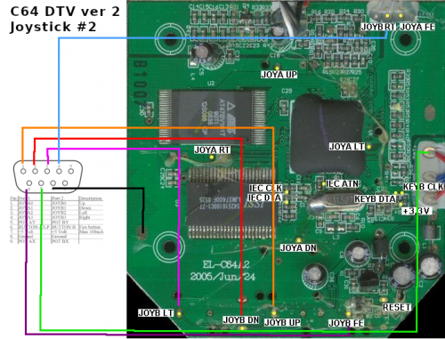
Joystick Port 2
Joystick port 2 is recommended to be in place, since most (unpatched) C64 games typically expect to find port 2 used for the controller on an original C64. It's also what the DTV joystick itself is normally connected to.
Note: +5v is only needed for some additional joystick functionality, most sticks don't use this, so it is safe to leave unconnected.
IEC / 1541 Disk Drive Connection
S-Video Connection & Fixes
As noted on the diagram, the connections are made to the solder points at each end of the capacitor marked C10.
PS/2 Keyboard Connection
Other Useful Diagrams
General C64 DTV Solder Points
Pinouts and diagrams of potential connections on the DTV (version 2) PCB:


