Table of Contents
PC-Chips M321
A pretty well specced 386DX motherboard which needs repairs. Then to upgrade it and run some benchmarks and tests.
Initial Thoughts
PC Chips!
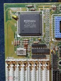
Ah, that electronics company that we all love to hate! They are notorious for putting up absolute rubbish, ripping off other designs and generally not playing very nice. The thing is, they didn't always use to be like this. During the 286 and 386 time period, although they did put out rebranded stuff, most of it was actually decent, or middle-of-the-road. Some of it was actually pretty good, too.
The PC Chips M321 motherboard is one of the few good examples during their earlier period of a pretty solid, good performing design. It has since been found that they used a relabelled Opti 82C391 chipset for this board (more info on that below) and actually, it's quite a nice design; good cache support, socketed CPU and FPU, full suite of 16bit and 8bit expansion ports, plenty of SIMM modules, etc.
This was one of a few motherboards I bought for very, very little money from that Russian auction site (https://streetmarket.ru) in early 2021. Again, like a lot of the others, it was cheap partly because it had some obvious minor damage…
Original Auction Images
These are the original images that came from the auction site (https://streetmarket.ru/) where I bought the board:
It has suffered what looks like minor to moderate battery leakage - though it appears to be limited to the area immediately surrounding the battery and potentially a few pins on the first ISA socket, the keyboard controller (and keyboard socket) and BIOS socket.
As long as it hasn't travelled much further, these should be possible to either clean or desolder and repair with replacement parts.
Some observations:
- No CPU (uses a 386DX PGA socket)
- No FPU (uses a standard 387 PGA socket)
- 4x 71256 (256x8kb) 32KB SRAM cache chips fitted (should be 128KB), could be expanded to 8x such chips and a TAG chip for 256KB.
- Battery damage: 5 pin DIN keyboard connector to replace
- Battery damage: BIOS socket to remove/clean and replace
- Battery damage: Keyboard controller to remove/clean and replace
- Battery damage: First ISA socket to remove and replace
- One SIMM socket of the pair closest to the edge of the board is damaged and will need replacing
- Various minor jumper headers are bent and need straightening/replacing
Arrival Pictures
[Update 10/03/2021] Motherboard arrived from Russia.
Corrosion around the battery terminals, keyboard socket and keyboard/BIOS chips is quite bad. I suspect I'll need to remove all of those components to clean/repair the board properly.
Slight damage to one of the SIMM socket plastic retaining lugs. This shouldn't pose a problem as the sprung metal tabs will keep a SIMM locked in place:
Motherboard Data & Variants
A summary of the motherboard capabilities follows:
| Item | M321 v1.x | M321 v2.x |
|---|---|---|
| Form Factor | Baby AT | Baby AT |
| Chipset | PC Chips | PC Chips (actually confirmed as a relabelled Opti 82C391) |
| Dimensions | 250mm x 220mm | 250mm x 196mm |
| Maximum RAM | 32MB (8x30pin) | 32MB (8x30pin) |
| Cache | 0,32,64,128,256KB | 0,32,64,128,256KB |
| FPU | 387, Weitek 3167 | 387, Weitek 3167 |
| CPU Type | 386 DX | 386 DX |
| CPU Speeds | 25,33,40MHz | 25,33,40MHz |
| Expansion | 6x16bit, 2x8bit | 6x16bit, 2x8bit |
The Opti 82C391 as used in the M321 V2.x has support in the UMBDVR software to make available UMB regions that can be used to load device drivers and DOS TSR's into:
Use the chipset flag /C=09 to specify Opti 82C391.
In addition, The Last Byte supports the chipset as well:
Repairs
Cleaning
The first job is cleaning, a good scrub with white vinegar to remove as much of the corrosion as possible, following by a thorough rinse with isopropyl alcohol:
Most of the corrosion was around the keyboard socket, battery terminals and pins/headers close to the BIOS/Keyboard ROM sockets, but after some heavy scrubbing, it's not looking as bad:
ISA slots have mostly cleaned up okay, may need to go back over a few spots with a smaller brush to get in some of the deeper sections:
There's a little bit of tarnishing on the AT power header:
The keyboard controller definitely didn't have much longer to live - it's heavily tarnished, but I'm hopeful that a good clean will remove it all:
Keyboard controller turned out okay:
Removal of corroded components
Next up is to remove the keyboard socket, plus any of those passive components around the battery terminals that look as if they have evidence of corrosion - mainly a couple of resistors and two diodes.
[Update 14/04/2021] - I tried a quick test of the board with just a POST diagnostic card and it immediately showed that the +12v line was not reaching the ISA slot. The board has some pretty rubbish electrolytic caps between the AT PSU header and the main power traces, so I took the opportunity to replace them - as well as the others on the board (about 10 or so in total).
Removal of keyboard socket, power supply capacitors (all 10uf, 25v) and the BIOS ROM:
The keyboard controller was also removed, as I'll replace the keyboard controller socket and clean the area underneath, so that any hidden battery damage is removed:
Keyboard controller socket removed to make it easier to clean the entire area:
[Update 16/04/2021] - Cleaned the remaining corrosion from the exposed traces and components around the battery area. There's at least one trace that no-longer has continuity - from the keyboard socket.
DIP sockets refitted, new 10uF capacitors fitted and new keyboard socket soldered:
Retesting
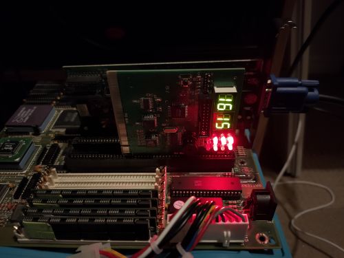
After replacing those components above, I tested again:
+12v and +5v are now happy, but -12v is missing and RESET seems to be being held. CLK also appears to be intermittent.
[Edit] The -12v signal seems to be down to the AT PSU header - a bit of corrosion and a worn connector; a quick 'wiggle' restores it; certainly nothing that would stop the board running. I'll revisit replacing the AT header at a later date.
Further Fault Finding
On closer examination and testing, there are a couple of cut traces on the reverse of the board around the cache sockets:
At least two of those traces have a very high resistance reading, so they probably need repairing.
Repaired the traces, but no further improvement to the status of the system, so I started looking elsewhere.
Checking Clocks
The flickering CLK signal on the POST card pointed to a problem with one or more of the clock generation circuits.
- Tested the 32KHz can: perfect
- Testing the 14MHz oscillator: erm… clock signal has gone bye-bye
So, the standard 14MHz oscillator is not giving a proper signal; that could certainly be an issue - many standard timings of the PC/AT are derived from that clock, so I needed to replace it. I quickly desoldered another 14MHz oscillator from another motherboard, and….
RESET no longer held, and a nice solid CLK signal. Excellent!
Also my Hantek USB oscilloscope confirms a 14MHz signal from the oscillator:
Checking BIOS ROM
Now I start looking at whether the BIOS ROM is corrupt or blank, so I fire up my trusty TL866 reader, pop in the BIOS chip and try to read it as either a standard 27C256 or 27C512, but no:
$ minipro -r file.bin -p "M27512@DIP28"
Found TL866CS 03.2.86 (0x256)
Invalid Chip ID: expected 0x200D, got 0xFFFF (unknown)
(use '-y' to continue anyway at your own risk)

$ minipro -r file.bin -p "M27256@DIP28"
Found TL866CS 03.2.86 (0x256)
Invalid Chip ID: expected 0x8904, got 0xFFFF (unknown)
(use '-y' to continue anyway at your own risk)
So, I peel back the sticker on the chip, and:
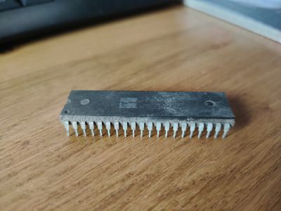
As if that isn't the cheapest looking knock-off EPROM you've ever seen. And what on earth is an M321F, other than “PC-Chips M321 Firmware” ???
I can't read the ROM, so I don't know what state it is in, or whether this is what is now causing the system not to boot/POST. I'll have to try replacing it and writing to a real EEPROM using the BIOS image from another M321 board, fortunately there are several linked on the UH19 website.
[Update 20/04/2021] - Programmed a new W27512 eeprom with a PC-CHIPS M321 bios image, and there's still no change:
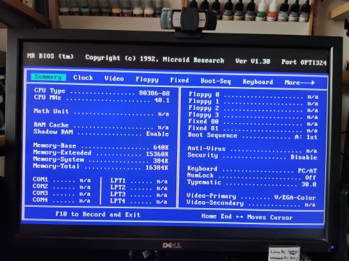
… but then I tried a MR BIOS image for the same Opti chipset as this board, and I actually get something out of it:
That says error code 03– (BIOS checksum) …
I decided to reflow the solder on the BIOS socket and recheck those jumper wires I fitted at the cache sockets… just retouching each of them to make sure they were properly soldered. Then tested again:
Not only that, but:
IT'S ALIVE, IT'S ALIVE!!! 
Final Fixes
So, it powers on, it displays stuff, and it seems that (at least) the MR BIOS ROM is working. However, there are still some issues:
- Keyboard doesn't work
- The 'cache address line' warning and lack of detected cache is a problem
After replacing the jumper wires around the cache sockets I get a bit more progress - the “Cache address line” failure is gone, but I have an odd-sized amount of cache showing:
There's also an error code 1615 showing:
That should be:
- 15: Keyboard controller failure - okay, we knew about this one
- 16: Size and test CPU cache - that makes sense, as the detected cache is wrong
Keyboard Controller Replacement
Amikey-2 to be fitted.
Cache Socket Trace Repairs
This clearly still isn't right, so we'll need to redo these repairs from scratch.
Configuration
Link to the motherboard data on the following sites:
V1.x Configuration
V2.x Configuration
BIOS Images
AMI BIOS
MR BIOS (for Opti 82C391)
Note: To use the MR BIOS version you need either a MR BIOS or AMI branded keyboard controller - alternatives, such as JetKey or Regional will not work; the system will boot (and the keyboard may work in DOS), but you will be unable to enter BIOS, change settings etc.
0 Wait State & Further BIOS Optimisation
Math Co-Processor
Speed Testing & Tuning
Configuration 0
- AMD Am386DX-40
- Cyrix cx87DLC-40 FPU
- 128KB Cache
- Default wait states, cache and memory timings
- 4x 4MB 60ns SIMMs
- VGA 1 - Trident 9000b 512k VGA
- VGA 2 - Tseng Labs ET4000AX 1MB VGA
- VGA 3 - Cirrus Logic CL-GD5428 1MB VGA
This is the default baseline configuration for the board with the most conservative BIOS settings.
Configuration 1
- AMD Am386DX-40
- Cyrix cx87DLC-40 FPU
- 128KB Cache
- Optimised wait states, cache and memory timings
- 4x 4MB 60ns SIMMs
- VGA 1 - Trident 9000b 512k VGA
- VGA 2 - Tseng Labs ET4000AX 1MB VGA
- VGA 3 - Cirrus Logic CL-GD5428 1MB VGA
Configuration 2
- AMD Am386DX-40
- Cyrix cx87DLC-40 FPU
- 256KB Cache
- Optimised wait states, cache and memory timings
- 4x 4MB 60ns SIMMs
- VGA 1 - Trident 9000b 512k VGA
- VGA 2 - Tseng Labs ET4000AX 1MB VGA
- VGA 3 - Cirrus Logic CL-GD5428 1MB VGA
Configuration 3
- Texas Instruments TI486DLC-40 - level 1 cache disabled
- Cyrix cx87DLC-40 FPU
- 128KB Cache
- Optimised wait states, cache and memory timings
- 4x 4MB 60ns SIMMs
- VGA 1 - Trident 9000b 512k VGA
- VGA 2 - Tseng Labs ET4000AX 1MB VGA
- VGA 3 - Cirrus Logic CL-GD5428 1MB VGA
Configuration 4
- Texas Instruments TI486DLC-40 - level 1 cache enabled
- Cyrix cx87DLC-40 FPU
- 128KB Cache
- Optimised wait states, cache and memory timings
- 4x 4MB 60ns SIMMs
- VGA 1 - Trident 9000b 512k VGA
- VGA 2 - Tseng Labs ET4000AX 1MB VGA
- VGA 3 - Cirrus Logic CL-GD5428 1MB VGA
Configuration 5
- Texas Instruments TI486DLC-40 - level 1 cache enabled
- Cyrix cx87DLC-40 FPU
- 256KB Cache
- Optimised wait states, cache and memory timings
- 4x 4MB 60ns SIMMs
- VGA 1 - Trident 9000b 512k VGA
- VGA 2 - Tseng Labs ET4000AX 1MB VGA
- VGA 3 - Cirrus Logic CL-GD5428 1MB VGA
Results
| Test | Config 0 | Config 1 | Config 2 | Config 3 | Config 4 | Config 5 |
|---|---|---|---|---|---|---|
| Processor Speed | 40MHz | 40MHz | 40MHz | 40MHz | 40MHz | 40MHz |
| Wait states | 1 | 0 | 0 | 0 | 0 | 0 |
| Norton Sysinfo CPU | ||||||
| Norton Sysinfo HDD | ||||||
| Norton Sysinfo Overall | ||||||
| CheckIt Dhrystones | ||||||
| CheckIt Whetstones | ||||||
| CheckIt Video chars/sec VGA 1 | ||||||
| CheckIt Video chars/sec VGA 2 | ||||||
| CheckIt Video chars/sec VGA 3 | ||||||
| CheckIt HDD Transfer | ||||||
| Landmark CPU | ||||||
| Landmark FPU | ||||||
| Landmark Video VGA 1 | ||||||
| Landmark Video VGA 2 | ||||||
| Landmark Video VGA 3 | ||||||
| 3DBench VGA 1 | ||||||
| 3DBench VGA 2 | ||||||
| 3DBench VGA 3 | ||||||
| ATPerf RAM Read | ||||||
| ATPerf RAM Write | ||||||
| ATPerf ROM Read | ||||||
| ATPerf Video Write VGA 1 | ||||||
| ATPerf Video Write VGA 2 | ||||||
| ATPerf Video Write VGA 3 | ||||||
| CompTest RAM thruput | ||||||
| CompTest Effective WS | ||||||
| CompTest MFLOPS | ||||||
| CompTest Video BIOS VGA 1 | ||||||
| CompTest Video BIOS VGA 2 | ||||||
| CompTest Video BIOS VGA 3 | ||||||
| CompTest Video Direct VGA 1 | ||||||
| CompTest Video Direct VGA 2 | ||||||
| CompTest Video Direct VGA 3 | ||||||
| CompTest Dhrystones |
Games Results
In addition, the following game benchmark results were recorded:
| Test | Config 0 | Config 1 | Config 2 | Config 3 | Config 4 | Config 5 |
|---|---|---|---|---|---|---|
| Wolfenstein 3D (FPS) | ||||||
| F1GP Bench 1 (CPU %) |
Software Versions
- Norton Sysinfo 8.0
- CheckIt 2.1
- Landmark 6.00
- 3DBench 1.0
- ATPerf 2.00
- Comptest 260
Notes
Conclusion
(Go back to the 386 PC main page)


