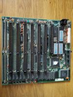
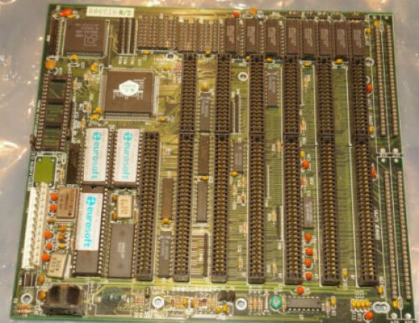
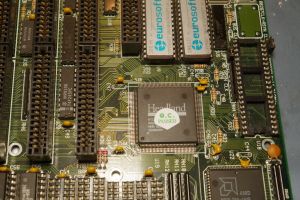
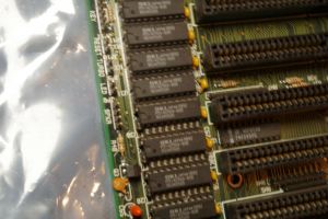
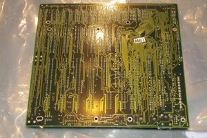
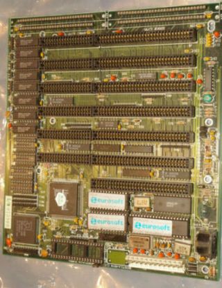
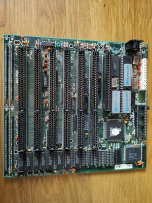
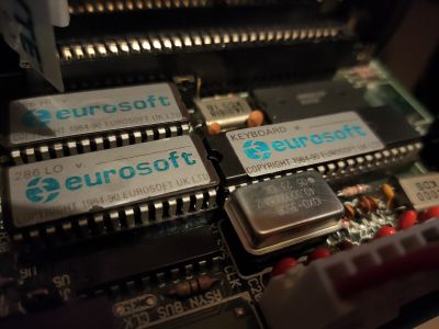
Eurosoft HT12HS (Headland HT12)
A variant of the common 286 Headland HT motherboard. With details on overclocking modifications and repairs, as well as benchmarks and testing.
Initial Thoughts
The HT12 286 chipset is well-proven, fast and has the advantage of allowing EMS memory use without a dedicated add-in card. It was what came on my first 286 motherboard, and at 16MHz was a strong performer; Wolfenstein 3D is easily playable.
This particular board popped up in my auction lists from the same seller as the Peaktron/PA286-SA1 board, and he did me a deal on the this motherboard since I'd already bought from him.
Things that I liked about it that drew me to it:
- It's a HT12 chipset: we know they are good
- It has 7 ISA slots (6x 16bit + 1x 8bit), one more than I'm used to; so extra space for either a SCSI card or EMS expansion
- Very clean and with no battery leakage at all
The concerns with this board are:
- It has SIPP sockets, not SIMM sockets
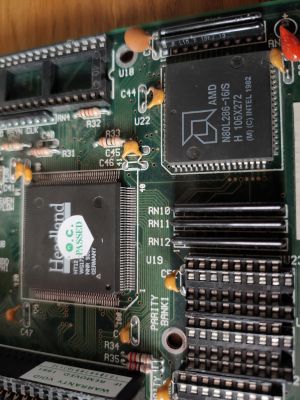
- It has a soldered-on AMD 286 16MHz
- HT12 chipsets don't normally go above 4MB memory support
One advantage to this 'Eurosoft' board, is that it seems to have at least two matches in the Total Hardware 99 guide, which means we've got a good chance of having at least one set of correct jumpers or technical data. It appears under two entries:
- Unknown G2-12HS
- INFORMTECH INTERNATIONAL, INC. Headland HT12
Differences between Eurosoft HT12 and others
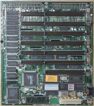
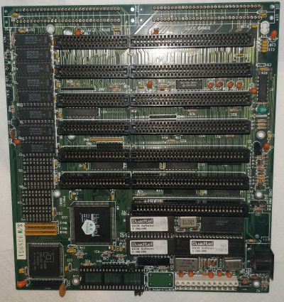
In order from left to right: Eurosoft HT12, Informtech HT12, Unknown G2-12HS HT12.
The only apparent difference between the difference boards are the BIOS labels, placement of board serial numbers and colour of some of the passive board components (resister networks, capacitors and similar). Functionality they would appear to be identical.
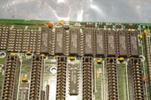
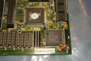
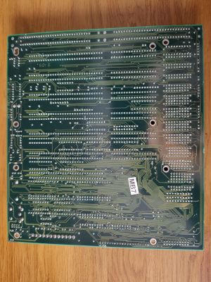
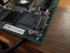
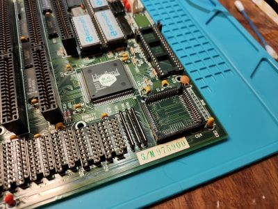
Detailed image of my board:
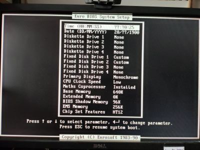
BIOS
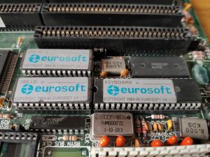
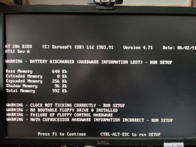
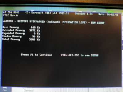
The Eurosoft BIOS appears to be custom - it isn't the usual AMI BIOS interface that you usually find on a Headland HT12 board:
Eurosoft UK Ltd was an early developer of BIOS software in the 1980's and developed the in-house Eurosoft BIOS which was licensed out to several OEM's and eventually bought by SystemSoft. It's fairly unique and unlike the typical BIOS you find on a low-to-mid range board like this.
- EuroSoft HT12 Low ROM: m5dsum 9b58b712849550c17b559d138e2093e9
- EuroSoft HT12 Hi ROM: md5sum c477104a7aaeaf4364d1a5fcc7e17714
- eurosoft_ht12.zip - Binary of the two ROM images. Each was stored on a typical 27256 (256kbit/8, 32KByte) EPROM.
Repairs / Remedial Work
Capacitor
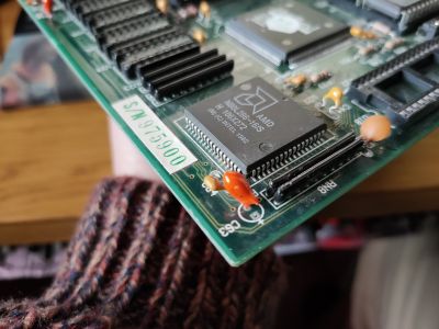
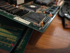
The board arrived with one tantalum capacitor snapped off the corner, right next to the processor:
I don't really have a problem with the seller or the packaging - this one is in such a position that even just taking it in or out of the anti-static bag could have pulled it over and snapped it. It's just a case of desoldering the remaining leg and fitting a new one. This definitely needs fixing as the board is very reluctant to POST and power-on in the condition it arrived.
The part appears to be a 10uF 16v Tantalum bead capacitor.
SIMM Sockets
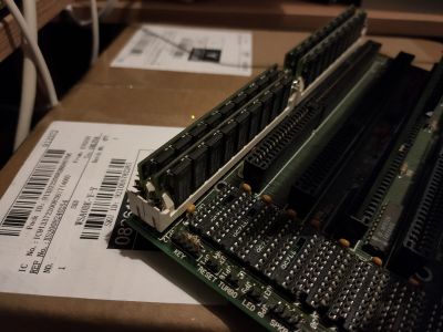
Temporarily fitted SIMM modules to the sockets and pushed them into the SIPP holes to test that it was working:
Hurrah!
DIP Socket for Oscillator
This was a soldered-in 32MHz clock, to test anything above 16MHz it had to be removed and a DIL/DIP-14 socket fitted in its place.
Processor PLCC Socket
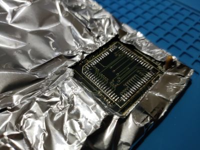
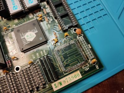
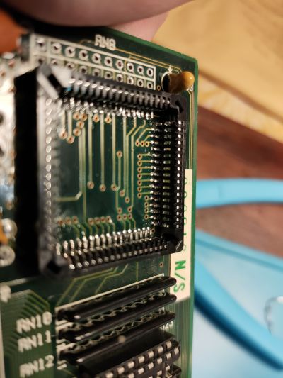
Processor is a soldered-on surface mount PLCC chip, so it had to be removed and a PLCC-68 socket fitted instead.
[Update 27/01/2021] - This was my first use of a hot air rework station (the cheapest on Amazon). I have to say that I am very impressed with how easily it works. There was a single damaged pad, and that was a free-floating unconnected pin, so nothing that needs repairing.
As usual, I found it was much easier to get access to the PLCC pins to solder by snipping out the central plastic support. I'm fairly happy with the outcome.
I had one bit of rework to do - on installing a processor I couldn't get the system to power on or POST - no beeps at all. I hooked up an oscilloscope and found that pin 31 (CLK) of the newly installed PLCC socket was just not quite making contact with the pad on the motherboard. That would explain it! :)
Reheated and flowed the solder on that pin and everything started working normally.
Configuration
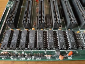
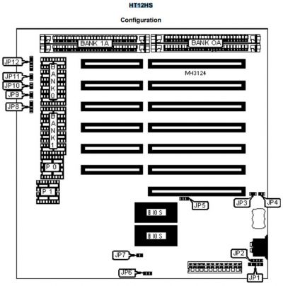
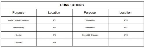
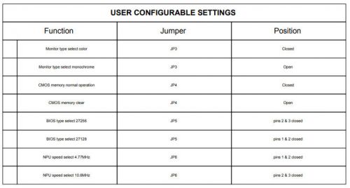
Front panel connections and basic system settings:
Addendum: On my board, JP6 is labelled as “80287CLCK=14.318MHz”. So my assumption is that pin 1-2 will reduce it from that speed. There is also a jumper, JP7 which is closed to disable FPU async mode.
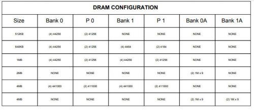
DRAM size options:
As usual with an HT12, there isn't an option for 8MB or 16MB configuration, nor a mixed DIP + SIPP/SIMM configuration.
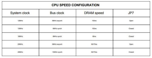
Processor / DRAM speed settings:
The good thing about all of these technical details is that it plainly shows configuration options for 20MHz operation, so the board should be capable of doing at least that (in all of the variants shown in the images earlier in the page, the hardware on the board is identical).
No valid configuration for memory sizes greater than 4MB, which is too bad. But we can always try it!
EMS / UMB Memory
As with most HT12 chipset boards, the Eurosoft HT12 can use the HT12MM.SYS EMS driver to map part of the (up to) 4MB of available RAM to Expanded Memory.
Just set the amount of EMS that is needed in the BIOS, reboot and the driver will automatically allocate a page frame and map the EMS ram.
In addition, or rather alternatively, you can gain 64KB of UMB (in place of the EMS page frame) by using The Last Byte memory manager and configuring it for an HT12 chipset. Then use hightsr to load drivers and other objects from config.sys or autoexec bat into UMB, just as you would use the normal DOS loadhigh or devicehigh command.
The HT12 does not, to my knowledge, support EMS and UMB simultaneously.
0 Wait State
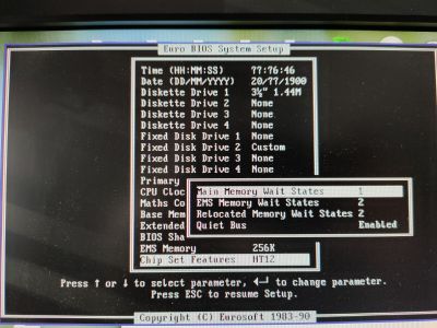
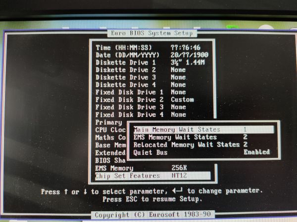
Zero-wait state configuration on this board is entirely software driven, as shown in this boards Eurosoft BIOS interface:
The default wait-state options are:
- Main RAM wait states: 1
- EMS wait states: 2
- Relocated RAM wait states: 2
The above will be the configuration we use as the baseline, unoptimised 16MHz config. For the optimised 16MHz config and higher, we will use:
- Main RAM wait states: 0
- EMS wait states: 1
- Relocated RAM wait states: 1
Math Co-Processor
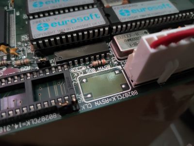
The board supports running the FPU at a different clock speed to that of the processor - except that my particular board lacks the seperate oscillator to do so.
To enable asynchronous FPU a DIP14 socket and seperate oscillator needs to be installed here:
Then, async operation is enabled via JP7, which is normally closed and runs the FPU at 14.318MHz. Opening the jumper should run it at the clock speed of the newly installed oscillator.
Care should be taken, as different floating point chips divide or multiply the incoming clock frequency in different ways. For example the Intel i287XL multiplies the incoming clock by 1.5 (they refer to it as 3/2 CLK). Do not use too high an oscillator frequency for the FPU chip.
For reference, this boards standard FPU clock of 14.318MHz will actually run my Intel i287XL at 14.318 * 1.5 = 21.5MHz, which is already pretty fast. I cannot imagine an FPU of this era working correctly at much more than that (perhaps 25MHz?).
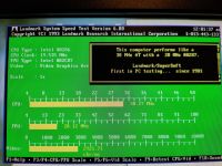
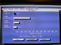
In benchmarking I will run FPU tests at the two speeds of the built-in oscillator:
- Speed A: 8MHz (default)
- Speed B: 14.318MHz (optional)
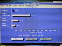
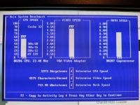
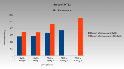
The results table at the bottom of the page show just how much of an impact the optional 14MHz clock has on the FPU - compared to an equivalent system, the FPU performance on this system is absolutely immense.
Speed Testing & Tuning
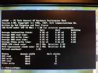
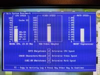
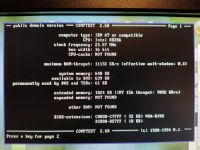
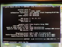
Configuration 0
- AMD N80L286-16S
- 32MHz oscillator (16MHz CPU speed)
- 1-wait state (1-wait state RAM, 2-wait state EMS and Relocated RAM)
- System + Video BIOS not shadowed
- Standard ISA bus clock
- 4x 1MB 60ns SIMM
- VGA 1 Trident TVGA9000 512KB VGA
- VGA 2 Tseng Labs ET4000AX 1MB VGA
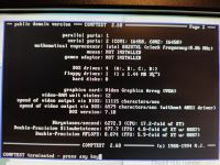
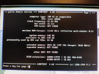
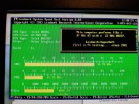
This a baseline configuration with zero-wait, standard ISA bus timings and BIOS shadowing disabled. It is intended as a 'worst-case', 'maximum stability' comparison.
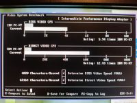
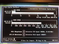
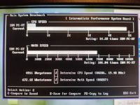
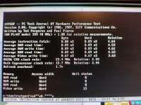
VGA 1
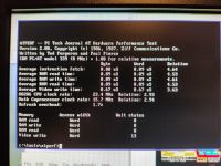
VGA 2
Configuration 1
- AMD N80L286-16S
- 32MHz oscillator (16MHz CPU speed)
- 0-wait states (0-wait state RAM, 1-wait state EMS and Relocated RAM)
- System + Video BIOS shadowed
- 4x 1MB 60ns SIMM
- VGA 1 Trident TVGA9000 512KB VGA
- VGA 2 Tseng Labs ET4000AX 1MB VGA
VGA 1
VGA 2
Configuration 2
- Harris CS80C286-20
- 32MHz oscillator (16MHz CPU speed)
- 0-wait states (0-wait state RAM, 1-wait state EMS and Relocated RAM)
- System + Video BIOS shadowed
- 4x 1MB 60ns SIMM
- Trident TVGA9000 512KB VGA
This is an identical configuration to config 1, except the processor is changed for a Harris-20, clocked at the same 16MHz as config 1.
I decided not to do any further testing of this configuration since all benchmarks prove that the Harris 286 is identical in performance to the AMD 286 at the same clockspeed (within insignificant margins of measurement errors, anyway).
Configuration 3
- Harris CS80C286-20
- 40MHz oscillator (20MHz CPU speed)
- 0-wait states (0-wait state RAM, 1-wait state EMS and Relocated RAM)
- System + Video BIOS shadowed
- 4x 1MB 60ns SIMM
- VGA 1 Trident TVGA9000 512KB VGA
- VGA 2 Tseng Labs ET4000AX 1MB VGA
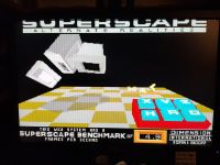
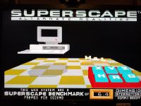
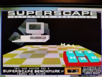
VGA 1
VGA 2
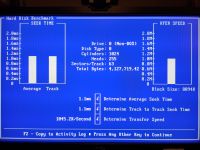
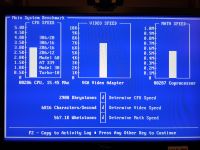
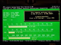
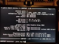
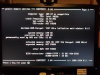
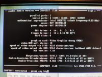
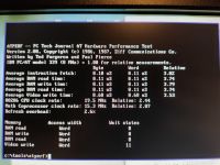
Note that the Comptest and CheckIt VGA results are incorrect in the above screenshots due to user error (I forgot to re-enable VGA BIOS shadowing). They are correct in the results table below.
Configuration 4
- Harris CS80C286-25
- 48MHz oscillator (24MHz CPU speed)
- 0-wait states (0-wait state RAM, 1-wait state EMS and Relocated RAM)
- System + Video BIOS shadowed
- 4x 1MB 60ns SIMM
- VGA 1 Trident TVGA9000 512KB VGA
- VGA 1 Tseng Labs ET4000AX 1MB VGA
I experienced a couple of crashes at 24MHz clock speed. This is likely to be the absolute outer limits of stability for the chipset and board. Even so, you probably wouldn't want to run at 24MHz. FPU, CPU and chipset were all warm but not hot to the touch; RAM was very warm, so it could either be chipset performance limitations or even RAM on the border of being stable. Perhaps it is worth cooling the RAM to see if it operates any more stable?
Note that the Comptest and CheckIt VGA results are incorrect in the above screenshots due to user error (I forgot to re-enable VGA BIOS shadowing). They are correct in the results table below.
VGA 1
VGA 2
I wasn't able to complete any benchmarks with the ET4000 fitted at this 24MHz processor speed.
[Update 17/02/2021] - I found that with a couple of specific SIMM modules and running the system from cold, it will run long enough to complete all the benchmarks, so the results below have been updated for the full set of 24MHz tests.
Configuration 5
- Harris CS80C286-25
- 50MHz oscillator (25MHz CPU speed)
- 0-wait states (0-wait state RAM, 1-wait state EMS and Relocated RAM)
- System + Video BIOS shadowed
- 4x 1MB 60ns SIMM
- VGA 1 Trident TVGA9000 512KB VGA
- VGA 1 Tseng Labs ET4000AX 1MB VGA
Unable to test. PC completes POST, but won't boot.
Configuration 6
- Harris CS80C286-25
- 50MHz oscillator (25MHz CPU speed)
- 1-wait states (1-wait state RAM, 2-wait state EMS and Relocated RAM)
- System + Video BIOS shadowed
- 4x 1MB 60ns SIMM
- VGA 1 Trident TVGA9000 512KB VGA
- VGA 2 Tseng Labs ET4000AX 1MB VGA
Tested and works, but slower than 20MHz with 0-wait.
Results
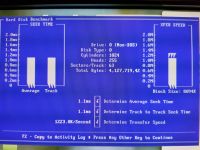
| Test | Config 0 | Config 1 | Config 3 | Config 4 | Config 6 |
|---|---|---|---|---|---|
| Processor Speed | 16MHz | 16MHz | 20MHz | 24MHz | 25MHz |
| Wait states | 1 | 0 | 0 | 0 | 1 |
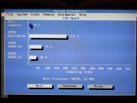
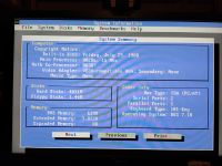
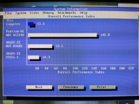
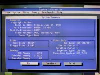
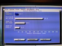
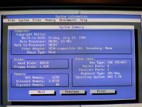
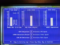
| Norton Sysinfo CPU | 8.7 | 11.8 | 15.9 | 18.1 | 14.0 |
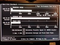
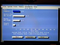
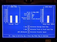
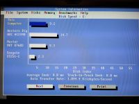
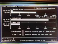
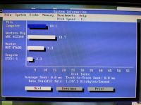
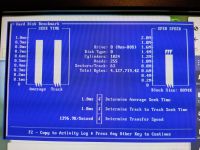
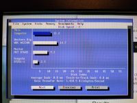
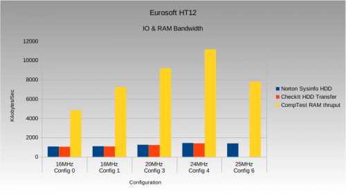
| Norton Sysinfo HDD | 1064KB/sec | 1094KB/sec | 1247KB/sec | 1428KB/sec | 1389KB/sec |
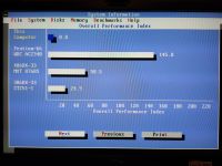
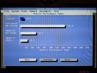
| Norton Sysinfo Overall | 8.8 | 10.8 | 13.3 | 15.7 | 12.9 |
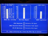
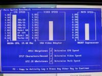
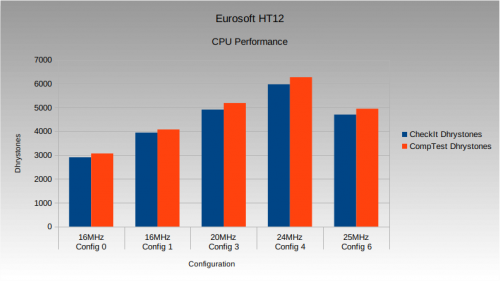
| CheckIt Dhrystones | 2908 | 3946 | 4911 | 5973 | 4702 |
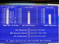
| CheckIt Whetstones @8MHz | 562.1K | 578.2K | 672.1K | 743.9K | N/A |
| CheckIt Whetstones @14.318MHz | 690.1K | 682.2K | 921.6K | 1102K | 1100.8K |
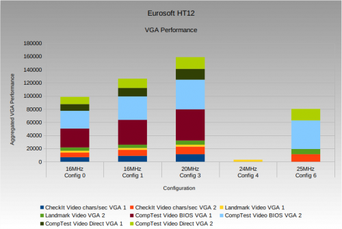
| CheckIt Video chars/sec VGA 1 | 6816 | 8860 | 11311 | 13632 | N/A |
| CheckIt Video chars/sec VGA 2 | 6995 | 9166 | 11557 | 13990 | 11311 |
| CheckIt HDD Transfer | 1045KB/sec | 1071KB/sec | 1223KB/sec | 1396KB/sec | |
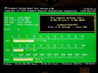
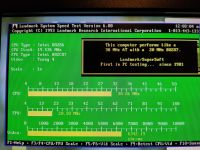
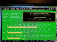
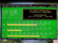
| Landmark CPU | 17.79MHz | 23.99MHz | 30.26MHz | 36.78MHz | 28.06MHz |
| Landmark FPU @8MHz | 17.73MHz | 17.87MHz | 20.10MHz | 21.75MHz | N/A |
| Landmark FPU @14.318MHz | 23.91MHz | 24.28MHz | 30.08MHz | 37.16MHz | 38.34MHz |
| Landmark Video VGA 1 | 2816.73 | 2816.73 | 2925.17 | 3006.24 | N/A |
| Landmark Video VGA 2 | 5015.51 | 5015.51 | 6342.19 | 7680 | 7992.20 |
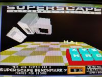
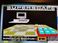
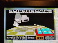
| 3DBench VGA 1 | 4.9 | 5.9 | 7.3 | 8.9 | N/A |
| 3DBench VGA 2 | 5.2 | 6.4 | 8.1 | 9.9 | 8.4 |
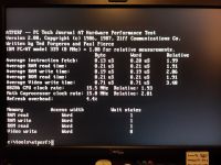
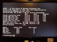
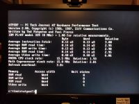
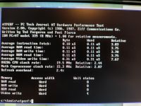
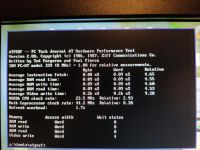
| ATPerf RAM Read | 1 | 0 | 0 | 0 | 1 |
| ATPerf RAM Write | 1 | 0 | 0 | 0 | 0 |
| ATPerf ROM Read | 1 | 0 | 0 | 0 | 1 |
| ATPerf Video Write VGA 1 | 8 | 8 | 11 | 13 | N/A |
| ATPerf Video Write VGA 2 | 4 | 4 | 4 | 4 | 4 |
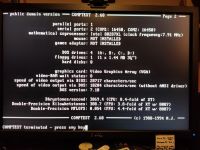
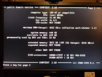
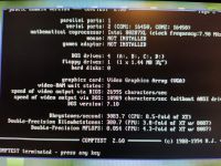
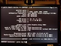
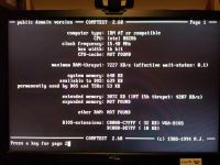
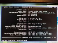
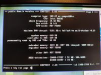
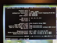
| CompTest RAM thruput | 4832KB/sec | 7227KB/sec | 9181KB/sec | 11132KB/sec | 7767KB/sec |
| CompTest Effective WS | 1.1 | 0.1 | 0.1 | 0.1 | 1.1 |
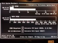
| CompTest MFLOPS @8MHz | 0.054 | 0.056 | 0.066 | 0.074 | N/A |
| CompTest MFLOPS @14.318MHz | 0.062 | 0.064 | 0.081 | 0.098 | 0.099 |
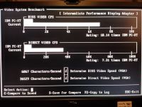
| CompTest Video BIOS VGA 1 | 28717 | 37759 | 47537 | 57642 | N/A |
| CompTest Video BIOS VGA 2 | 26995 | 35564 | 45026 | 54483 | 43388 |
| CompTest Video Direct VGA 1 | 10204 | 12987 | 16393 | 19688 | N/A |
| CompTest Video Direct VGA 2 | 10989 | 14085 | 17857 | 21739 | 17544 |
| CompTest Dhrystones | 3069.4 | 4077.6 | 5187.5 | 6272.3 | 4947 |
Games Results
In addition, the following game benchmark results were recorded:
| Test | Config 0 | Config 1 | Config 3 | Config 4 | Config 6 |
|---|---|---|---|---|---|
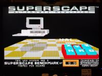
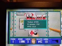
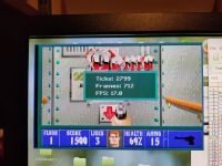
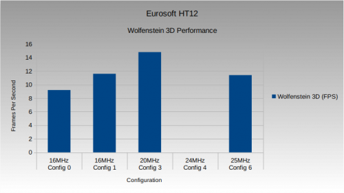
| Wolfenstein 3D (FPS) | 9.2 | 11.6 | 14.8 | 17.8 | 11.4 |
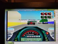
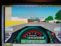
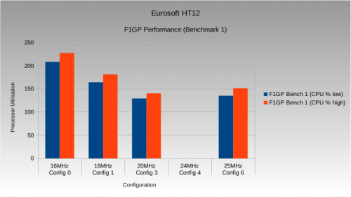
| F1GP Bench 1 (CPU %) | 208-227 | 164-181 | 129-140 | 108-118 | 135-151 |
Software Versions
- Norton Sysinfo 8.0
- CheckIt 2.1
- Landmark 6.00
- 3DBench 1.0
- ATPerf 2.00
- Comptest 260
Youtube Clip
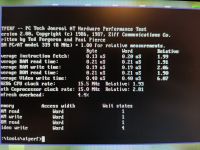
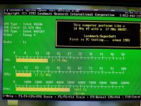
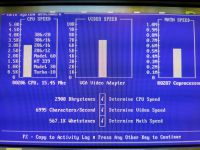
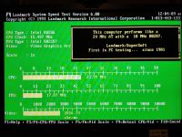
This footage shows BIOS boot screen, benchmark results from Landmark, Comptest and ATPerf. As well as a demo of Wolfenstein 3D in benchmark mode and a longer playthrough of the original Wing Commander game.
All footage taken using the stable 20MHz, 0-wait state configuration (Config 3).
Conclusion
As long as you don't push this board beyond its limits (20MHz with 0-wait states), it's very stable and in a like-for-like comparison, pretty quick.
It's not going to compete with super-clocked 30MHz systems, or those that can run stably at 25MHz, but it represents a significant speed up over the vast majority of 16MHz clocked 286 systems;
- The RAM speed is very good
- It has comprehensive extended, expanded and BIOS shadow support
- If you use the HT12MM.SYS driver you can get EMS in DOS
- If you use “The Last Byte” you can get a 64KB UMB to load drivers into (but not at the same time as EMS)
- It has better wait-state tuning options that most HT12 motherboards
- The ability to run the FPU at different clock frequencies makes for excellent FPU performance at the faster of the two onboard speeds (14.318MHz) when used with a 3/2 internal multiplier FPU like i287XL models
On the downside there don't appear to be any options to change the ISA clock speed (at 20MHz CPU speed, what is it running at?) and it just cannot make 25MHz. My guess is that 22Mhz or thereabouts is the limit of the chipset at 0 wait states. It can indeed run at 25MHz, but to do so involves setting the 1-wait state BIOS option which kills performance and, other than some oddball metrics, brings performance down to somewhere between 16 and 20MHz. i.e. there's no point to running at 25MHz on this board unless you are FPU limited… and… quite why are you running FPU code on a 286 in the 21st century?!!!!
If you want a fast, reliable 286 with readily available chipset drivers, then this is one of your best options. If you want to build one of the fastest 286 systems, then this probably isn't the one you want.
(Go back to the 286 PC main page)
