Table of Contents
PyCosworth
Note: The programme and its source code are freely available and hosted at: https://github.com/megatron-uk/PyCosworth
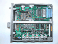
PyCosworth is a monitoring, data-logging and diagnostic tool for (primarily Escort/Sierra Cosworth) vehicles equipped with the Magneti Marelli L8/P8 ECU which have the serial datastream protocol enabled.
Quick Links:
- General overview, Hardware & Software requirements - keep reading this page
This feature is often called the Pectel Datastream, but is simply a feature of the ECU itself - being turned on or off based on the type of ROM chip fitted to the ECU. Some aftermarket ROM chips available from tuning firms can optionally enable this feature where it was not available by the manufacturer.
PyCosworth interfaces with the serial connection to display, monitor and log the information available via that datastream, similar to such products as:
- The SECS Monitor
- RP Labs IAW Monitor available from RPLabs or Motorsports Developments
These products are great for their intended use, but are either a: very expensive, or b: designed for use on a laptop. PyCosworth is intended to to on a cheap embedded device such as a Raspberry Pi, BeagleBoard or other small Linux system and be permanently connected to the vehicle.
Hardware Requirements
In addition to my software, you need a few key pieces of hardware in order to access the sensor data from your Cosworth ECU:
- A vehicle with a serial datastream enabled Magneti Marelli ECU, specifically:
| Model | ECU Type |
|---|---|
| Ford Sierra Cosworth 4×4 | Weber/Marelli L8 ECU (with serial comms enabled via software) |
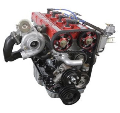
| Ford Escort Cosworth | Weber/Marelli P8 ECU |
Note: Any other Cosworth YB engine with one of the above ECU variants retro-fitted should also work.
- A diagnostic cable that interfaces with the ECU.
- Please note that these are specific diagnostic cables that connect to the 3 pin flash-code cable on the factory Ford loom, convert it to a RS232 compatible serial interface and then convert that serial interface into a USB plug for use on modern computers. Common OBD/OBDII interfaces will not work with the Weber Marelli serial datastream. Ask your usual Cosworth specialist or forum on how to obtain one.
- A Linux computer running Python (both 2.x and 3.x supported) with at least one free USB port for the USB to RS232/TTL diagnostic cable. A basic laptop will be fine - the application is not memory, cpu or graphically intensive.
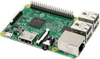
- Optionally: A Raspberry Pi (1/2/3, A, B or B+) with exposed GPIO pins to use optional in-car push buttons to control system functionality instead of a laptop. Without buttons you will not be able to control the application if you have an embedded system like the Pi. A total of three buttons are reccomended:
- Button 1: Start/Stop data logging
- Button 2: Cycle to next sensor display
- Button 3: Restart ECU comms
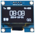
- Optionally: A SSH1102 or SSD1306 miniature OLED screen supported by the Python luma.oled driver (the 1.3“ screens with 128×64 pixels are strongly reccomended) for in-car live sensor/data visualisation.
- Optionally: A supported X11 display or desktop interface to emulate the live sensor/data visualisation as would be seen in the OLED screens, in a desktop window.
- Optionally: A Super Watchdog V2 watchdog/UPS hat addon for the Raspberry Pi in order to handle random power-off events whilst using the system in a car, and to shut the system down safely when the ignition power is disconnected.
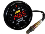
- Optionally: An AEM Wideband X-Series Air Fuel Ratio sensor and gauge with serial datastream output. You will need a secondary USB to RS232 adapter for the AEM sensor/gauge.
- Optionally: A Digispark ATiny85 USB development board running the I2C-tiny-usb firmware to connect and prototype I2C connected OLED screens on a desktop PC. This is for development of the UI on OLED devices when not using a Raspberry Pi (laptops/desktops do not normally have a user-accessible I2C interface. It is not needed to run the software normally.
None of the optional components are necessary in any way to run the software, but functionality will be limited to text-mode display and datalogging to file and the requirement of using a laptop. One of the main goals of this project is to do away with the need for a laptop.
The addition of an AEM Wideband sensor and gauge makes it possible to simultaneously log AFR data at the same time as the main Cosworth ECU sensors. If you have another device that you wish to add support for, please let me know.
It it not designed to work (and I have no way to test) on the Fiat/Lancia or Ferrari F40 version of the Magneti Marelli ECU, but may work. However, an excellent tool already exists, that the comms protocol part of PyCosworth is partly based on. Many thanks to Neil, the author of that tool, for his technical information.
Hardware Configuration Guide
There are too many variables to say “this is exactly how to do it”, but I've documented how my setup is connected together in this hardware setup guide.
Software Requirements
All of the Python software library requirements are listed in the requirements.txt file, simply run:
pip install -r requirements.txt
… to install them on your Linux system.
On Raspbian systems, first check the my Raspberry Pi software guide for any pre-requisites needed. There are several software packages needed to support the hardware devices used on that platform.
The guide also lists a number of software configuration changes you may need to make to your Pi in order make it boot faster as well as increase speed of data display and enable the optional hardware listed above, to work.
Running PyCosworth
To start the monitoring programme, type:
./SensorDashboard
in the programme directory. The monitor will start and within a few seconds it should communicate with the ECU and start gathering data.
Normal Interface
At start up a short banner message will be shown whilst sensors and graphics are loaded and initialised.
After initialisation is complete, the application will immediately move to the first defined sensor that is set in the [the configuration file](docs/Configuration.md).
You can cycle through the available Cosworth sensors:
- AMAL valve duty cycle, in percent
- BAT Battery voltage
- CO Base Fuelling, in percentage increase over base level
- ECT Engine Coolant Temperature, in degrees centigrade
- IAT Intake Air Temperature, in degrees centigrade
- IGNADV Ignition Advance, in degrees
- INJDUR Injector Pulse Width Duration, in milliseconds
- MAP Manifold Pressure, in millibars (or PSI, if configured via settings)
- RPM
- TPS Throttle Position, in percentage open
… with a single press of Button 2 at any time. In addition AFR is available if you have enabled the AEM Wideband sensor support. The current sensor is highlighted in the upper left corner of the display.
The units the sensors are reading in are automatically shown to the right of the sensor value; whether this is a percentage, degrees centigrade, voltage, millibars or some other unit.
Comms Errors
If, on starting the application the cable is not fully connected to the ECU, or the vehicle ignition is not live a warning message will be displayed in the lower left corner of the screen.
You can press Button 3 to re-establish communication links with the supported sensors (Cosworth ECU and AEM Wideband AFR) without powering the device off. Whilst comms are being restarted a wait message will be shown on-screen.
Datalogging & Demo Functions
You can access a demo mode to test your hardware by running the application in demo sensor mode (see the link to the configuration file, below) - this generates a never-ending stream of bogus sensor data for each of the sensors you have activated. Demo Mode is indicated by the status display in the top right corner of the screen.
In addition, you can start or stop logging at any point in time by pressing Button 1 and a log of the active sensors will be recorded to disk/SD card. Logging Mode is indicated by the status display in the bottom right corner of the screen.
The file that the sensor data is recorded to is an industry standard comma-seperated-value text file:
The Counter column is the sensor-reading pass that recorded the data. From the point at which the ECU is connected, the data is continually sampled; each pass having a unique ID for the duration that the device is powered on.
The Time column is the time relative to the first sensor reading. Since the Raspberry Pi and other similar embedded devices do not have clocks, there is no guarantee we can use a HH:MM:SS format, so we record each log of sensor readings as an offset (in seconds) from the first reading.
Configuration
All of the user-customisable settings are found in the file
libs/settings.py
within the programme directory. This includes an extensive set of optional modules and complete customisation over which sensors are monitored, their update frequency (subject to the speed of the ECU) as well as total control over the layout and display modes of the in-car visualisation and display options.
Please see the configuration guide for full details.
Pectel Datastream
For full details of the Pectel serial datastream that I have found, see the Cosworth Pectel datastream protocol document.
