Sharp X68000 Pro - PSU Replacement & Troubleshooting
The wonderful Sharp X68000 has a bit of an achilles heal; the power supplies are made of cheese. Soft cheese at that.
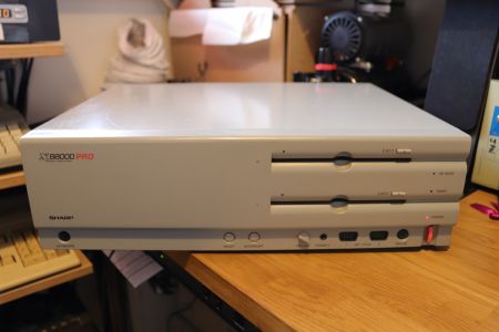
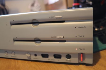
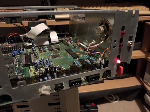
I imported a fairly decent X68000 Pro from Japan in May 2020 and of course, on arrival, it wouldn't power-up, just sits at the red power LED:
Sadly, this is all too common. Looking on Yahoo Auctions Japan almost all of the X68000's that are listed and are not mega-bucks are in the same state; “Power light is on - untested”. It pretty much means the same thing every time: dead PSU.
The Plan
- Remove the internal 110V AC PSU
- Fit a 90-120w Pico PSU
- Plug Pico PSU into an Aranet ATX to X68000 adapter
- 12v DC barrel jack mounted on rear of case
This lets me free up space inside the case used by the original PSU, removes the reliance on a 240v to 100/120v stepdown convertor (I was borrowing the one I use on my PC-9821 for testing the X68000), gets rid of a part that is old, unreliable and produces significant waste heat.
Pico PSU
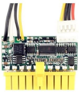
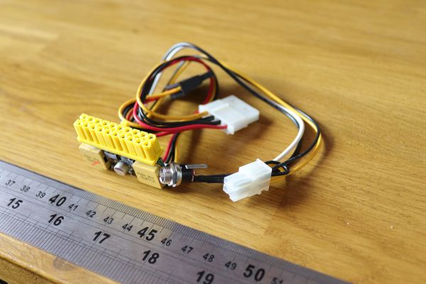
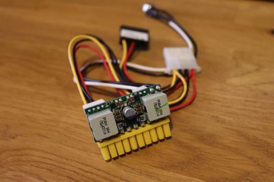
Here's the Pico PSU, a 90w model, you can find them everywhere. Ebay and Amazon have them listed all the time:
Manufacturers image and the actual part that arrived. It really is tiny!
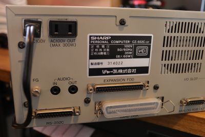
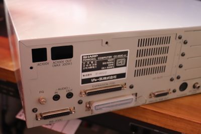
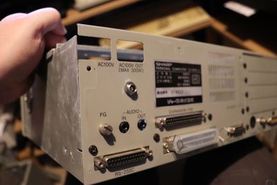
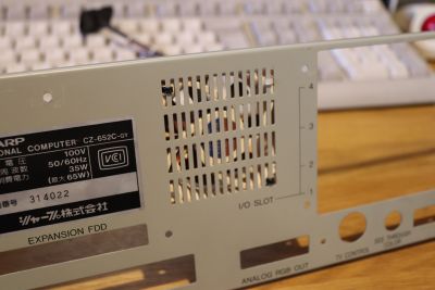
According to the specs on the rear of the X68000 Pro case…
… PSU is only rated at 35-65w, so the additional overhead of the 90w (peak) PicoPSU should give us plenty of safety margin.
12v DC PSU
The 12v DC power supply for the Pico PSU is a relatively boring brick; 12v, centre positive, 7.5 amps maximum.
Mine came from a supplier of laptop power supplies on Ebay, but it's just a standard 12V, there's nothing special about it.
Aranet ATX to X68000 Adapter
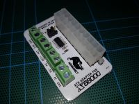
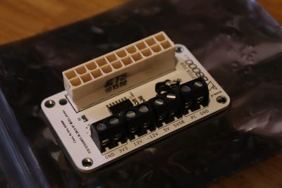
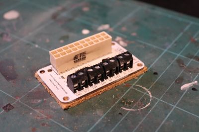
ATX adapter as sourced from Edu Aran of Aranet:
This lets you plug a standard ATX power connector into a X68000. Well, technically it allows you to plug it in, does some trickery with the 5v standby line and then breaks out the X68000 power lines into standard screw terminals that you then attach your original X68000 internal power cables to (one for the motherboard, one for the hard drive [if you have one], and then for the floppy drive[s]).
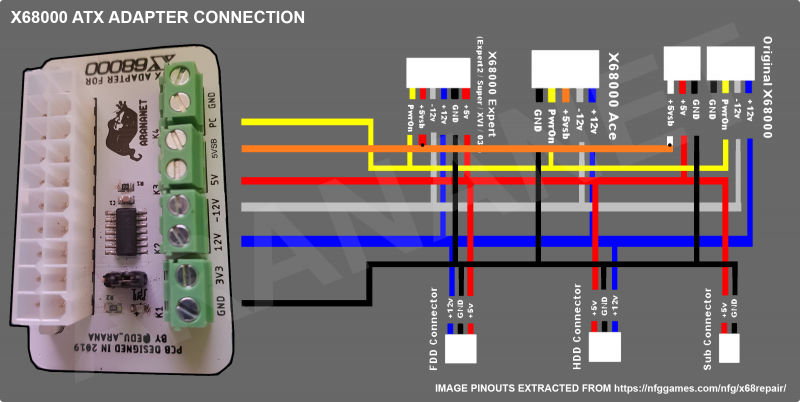
Edu also links to the following colour guide for connecting the ATX adapter to the internal cabling of various X68000 models:
[16th June 2020] - Order confirmed as shipped by Aranet.
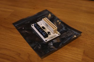
[Update 24th July 2020] - Postal service finally delivered the ATX adapter from Edu:
That's a long time to get from Spain to the UK… wonder which postal hub it has actually been sitting in!
Fitting the New Components
Removal of Original PSU
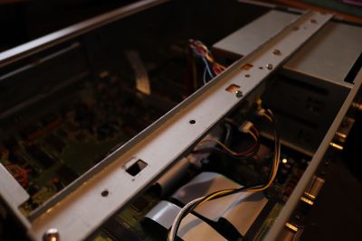
The original power supply comes out easy enough; take the case cover off as normal. Note that the two left-most black screws go through the case into the PSU, so they won't go back in again once it has been removed. After the case cover is off, remove the rear-most support bar which is screwed to both the PSU and the IO slot housing.
Disconnect the motherboard power cable and the two floppy drive 4-pin Molex power cables. The PSU should lift upwards - there are no hidden connections or anything else to take out.
Once it has been taken out, refit the support bar - you'll have a spare machine screw where it was attached to the PSU.
The rear of the machine is left looking like this:
Note the missing black case screws at the left and above where the PSU was fitted - the case itself isn't threaded and these screws relied on a threaded housing in the PSU. They're not needed to keep the cover secure - the main side screws and the remaining black screws will do that easily enough. It might be an idea to glue/tape them to the inside of the case (in a little ziploc bag) just for any possible refit in the future.
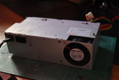
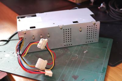
The PSU is a fairly non-descript unit - the fan is visible, as well as one end of the unit being open. Other than that it has the motherboard power cable, two FDD 4-pin Molex plugs and one auxilliary plug which doesn't appear to be used on a non-HD machine:
If you were intent on servicing the original PSU (why???) then be warned that at least on my unit the machine screws that held the cover plates on were extremely tight (possibly compounded by oxidation of the metal/screws), and I couldn't undo them by hand.
Also, be aware that the power supply for the Pro model is completely different to that of the tower (X68000, Ace, XVI, Super); the latter being somewhat of an 'L' shape compared to the plain rectangular design for the Pro, so they are not easily swappable.
Examining the PSU
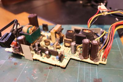
[July 2020] It came time to fit the new PicoPSU and bits and pieces, but to do that I needed to retain the original wiring from the PSU… I thought it would be interesting to see what was wrong with it.
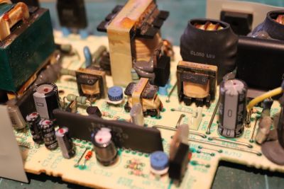
At first glance it looks reasonable, no spectacular exploded caps or anything like that.. though around the base of several it looks a little oily:
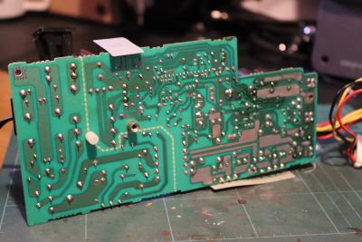
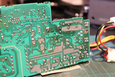
Let's flip the board over and see if there's anything underneath….
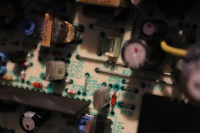
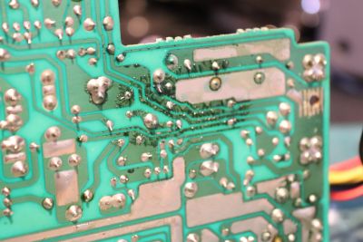
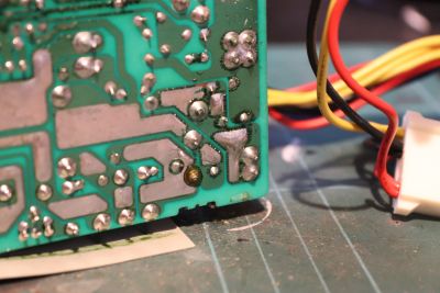
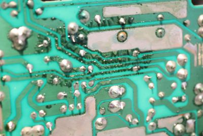
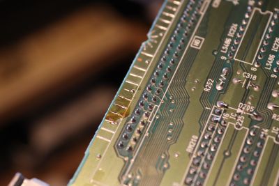
Oh my! That's about the worst case of capacitor corrosion I've ever seen! And just for kicks, here's a set of zoomed in images showing just how much damage to the PCB that the leak has caused:
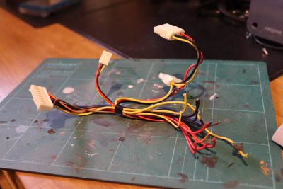
Original Power Cables
We need the original internal wiring, as though the drives have standard 4-pin Molex connectors, the motherboard doesn't use anything remotely standard compared to the PC world.
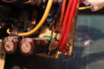
With the PSU removed, snip the wiring as close to the PCB as possible:
Aranet ATX Board Install
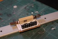
Firstly I insulated the underside of the Aranet board so that any danger of it shorting out would be minimised:
I just used some cork mat that I had, but foam padding or similar should work just as well - you want something with a bit of 'give', to account for the underside of the pins/solder.
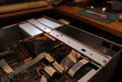
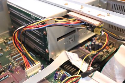
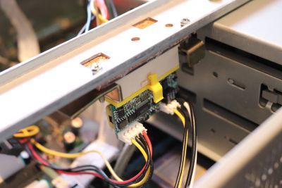
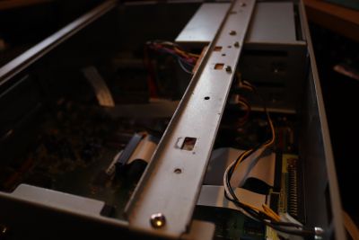
I decided to mount the board to the underside of one of the strengthening braces which run across the top of the case. This one, in particular, was used to fasten the original power supply to, so there was a big area of dead space underneath it. Perfect for the board and wiring to be located. I even managed to reuse some of the original fasteners that were in the dead PSU:
Also it means that it is removeable, should it ever need replacing.
PicoPSU Install
The barrel jack for the DC +12v input to the PicoPSU was fitted to the rear of the machine, just below the original AC input
Better put a sticker on there too, to label the input (with a PicoPSU, it should be +12v DC, positive tip).
Internally, the PicoPSU then just plugs into the Aranet board. The 4-pin Molex connector can be used to power the floppy drives directly.
Reconnecting Cables
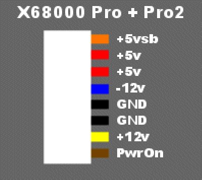
This is where the first problem arose; the X68000 Pro doesn't share the same wiring standard as the other models. Fortunately, Gamesx has a nice original diagram of the PSU, including the colours and their function:
Here's a coloured version of the above PDF:
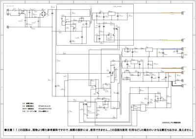
| Colour | Voltage | Current Rating | Function |
|---|---|---|---|
| Orange | +5v | 500mA | SUB_POWER / Standby / SB |
| Yellow | +5v | POWER_CONTROLLER / PC | |
| Blue | +12v | 3A | |
| Brown | -12v | 500mA | |
| Red | +5v | ||
| Black | Ground |
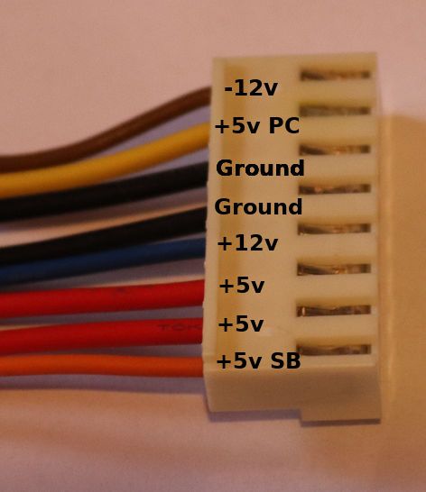
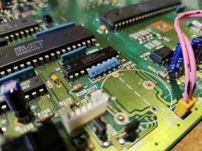
And here's the same thing, labelled on the actual motherboard connector itself:
Here's the Aranet board with the original wiring connected up:
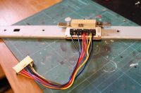
This is all completely WRONG. The Pro PSU schematic colour codes are incorrect! The actual, correct colour codes are here.
Replacement Cooling Fan
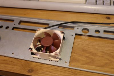
By all accounts it isn't needed with a PicoPSU, and the X68000 itself is hardly a furnace in terms of power consumption, but to keep things correct I've fitted a Noctua 60mm fan to the vents on the rear panel. I guess the idea is that it will pull heat out of the case, from over and around the PicoPSU, since it's mounted directly behind the fan.
Fan is just attached with zip ties, since I didn't want to have to drill loads of holes if they weren't strictly necessary.
Testing!
Connected up a minimal system (no floppies, no add-in cards), and left the case off:
So what happened?
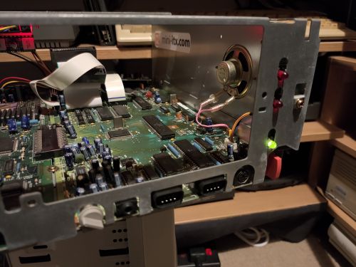
Well, the good news is that it does more than just put the red standby light on. It started up and showed a green power light… and then promptly this happened:
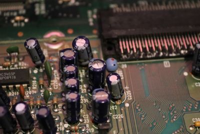
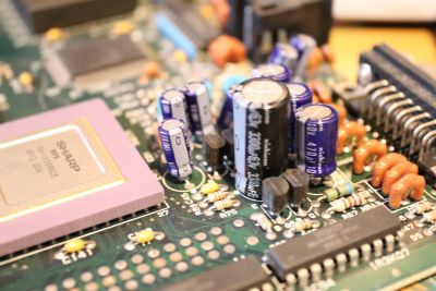
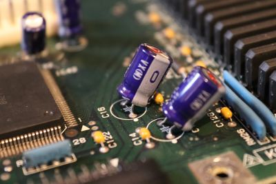
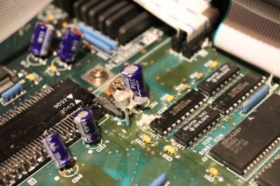
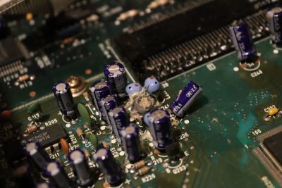
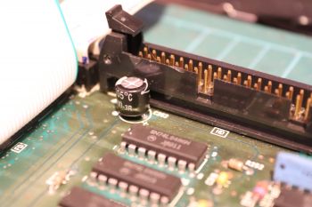
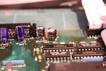
Capacitors C227 C241 and C243 blew and went bang 
Re-Checking
Okay, I'll have to recheck the entire system now. But that means taking it apart. Unlike a PC or a Mac, these things are really not designed to come apart.
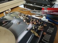
To give you an idea of how much effort it is. Here is the pile of screws that are taken out:
Argh!!!
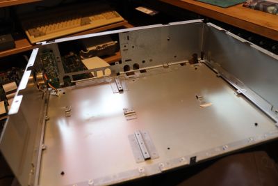
… this is what the empty X68000 Pro case looks like:
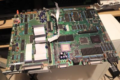
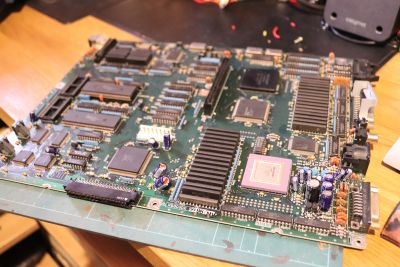
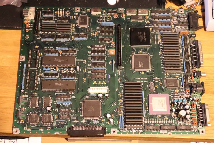
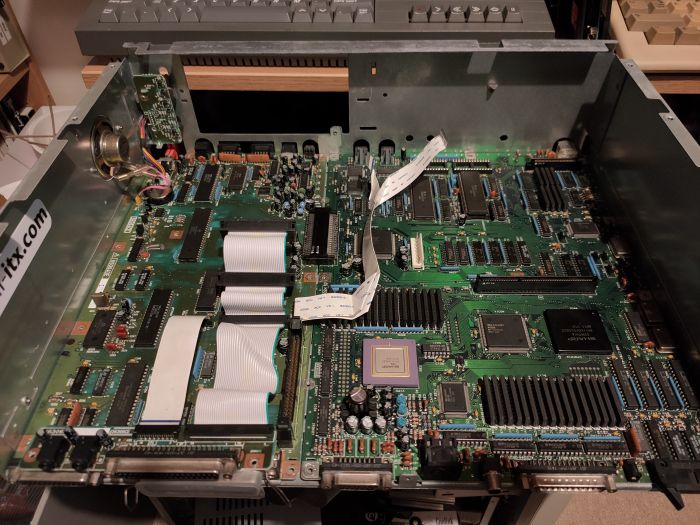
… and the main and sub-boards in all their glory:
The main board, which contains the main processor, video processors and memory doesn't have a lot of capacitors to check:
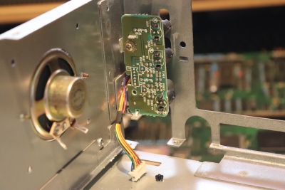
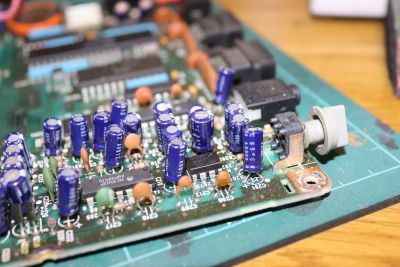
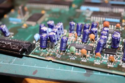
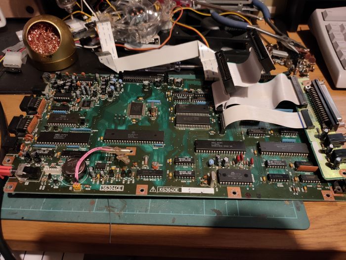
This is the sub-board, which is mainly IO, sound hardware, front panel connectors, etc. There are 35 separate electrolytic capacitors on this board :(
This is the board where C227 and C243 failed.
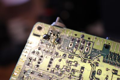
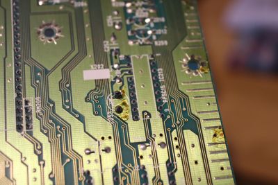
There is some discolouring on the reverse of the board, but I'm certain that this is actually just flux since it is hard to the touch:
Next Steps
[Update July 27th 2020] - All replacement capacitors ordered from Farnell, now it's a case of waiting. I suspect what I'll do when they arrive is replace the two failed caps and try it again. While I'm on doing that I'll also take the opportunity to replace the soldered-on lithium coin cell battery with a holder and a removable (but still rechargeable) ML2032 cell.
[Update July 30th 2020] So….
… that didn't work. 
Same as before; C241 and C243 blew within seconds of being powered on. Standby works; the red light comes on. It powers on and turns green, but within seconds the speaker crackles and those two caps blow.
I am actually coming round to the possibility that it may be that the PicoPSU may be faulty… I've measured the output voltages and they are:
- +5v Standby : +4.9-5.02v
- +5v Power Control : +4.9-5.02v
- +5v : +5.02v
- +12v : +12.2v
- -12v : -15.6v !!!!!
Replacement PicoPSU
[Update July 31st 2020] - Ordered a new official PicoPSU from Mini-ITX.com and am currently waiting for delivery. This one will definitely be getting checked before being connected…
[Update August 1st 2020] - Replacement PicoPSU arrived:
Voltage readings from this one with no load measured the following:
- +5v Standby : +5.06v
- +5v Power Control : +5.06v
- +5v : +5.06v
- +12v : +12.2v
- -12v : -13.6v
I replaced C241 and C243 again, and tested the X68000 one more time - pop went the capacitor (only C243 this time) again.

This is getting downright depressing.
Disengage Moron Mode
Yeah. I'm a moron. I should have read the full documentation. The wiring colour for the X68000 Pro PSU schematic is NOT correct.
The actual wiring colours are listed here, and are:
You'll note that the wiring of the motherboard power connector does not match that of the PSU schematic, which was:
- Orange: +5v Standby
- Yellow: +5v Power Control
- Blue: +12v
- Brown: -12v
- Red: +5v
- Black: Ground
The PSU PDF actually shows +5v PC and +12v transposed, as well as -12v and +12v. No wonder the thing was popping caps every time it was plugged in! I really should learn to check and double check my sources, as it's clear that each source of information contradicts each other.
Here's what a naked X68000 Pro looks like with power applied… and wired correctly:
Quick clip of the power control panel reacting to wall power being plugged in and the front power button being pressed:
Next: Connect back up the various peripherals (floppies, video out, keyboard, etc) and see whether there has been any damage, or (if I'm extremely lucky) see if this thing is actually running. 
Before I forget... Backup Battery
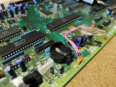
Fitted a coin cell holder in place of the original soldered-on SRAM battery:
Instead of fitting diodes and other things to stop a generic CR2032 coin cell being charged, I fitted a rechargeable ML2032 instead.
Further Testing
Video Output
Connected up a Sanwa AD-D15NE DA-15 to HD-15 adaptor and plugged the X68000 into the OSSC:
It's alive!!!!
There's still some noise from the onboard speaker, as well as through headphones via the back panel stereo jack, so there's likely further caps that need replacing around the audio circuitry (not surprising, since they've had the wrong voltage going through them), I just hope that none of the actual audio IC's are bad.
Keyboard
There's no lights showing on any of the PS/2 keyboards I've tried (I'm using the Aranet PS/2 adaptor), and, curiously, my KVM switch also doesn't detect a keyboard signal coming from the X68000 either… and it's usually pretty clever about detect whether there's a keyboard signal or not.
Fault tracing is probably going to start by seeing if there's any voltage at the front panel keyboard port.
Floppy Drives
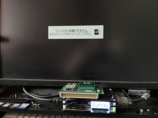
Well, the drives at least do the power-eject routine ok, they also appear to at least do an initial read on boot. But then I get this:
This is using the Masterdisk_V3.xdf startup disk, used to set up a new X68000 with a basic Dos image.
I've excluded the MIDI, SCSI and XSIMM cards, so it's definitely none of those that are causing the issue. The only thing that has me slightly worried now is that the second floppy drive doesn't appear to read the floppy - it almost immediately ejects it. I wonder if that drive is not registering as present with the system?
If I test the system using a self-booting disk (i.e. one that doesn't boot to Human68k DOS), then it appears to work:
Drive 0 loads the disk, and the game loads. I even hear audio, though it's very quiet and has to have the volume pot turned all the way up. At the very least, the core functionality of the system seems intact; RAM, CPU, floppy (at least drive 0, anyway), audio chip etc.
Okay, lets replace ALL capacitors
[Update - August 3rd 2020] - Since there seems to be ongoing issues with the system, the only thing that makes sense to do at this point is to replace all capacitors.
For the full list of caps on the main board, refer to the my X68000 Pro capacitor list page.
Main Board
Start with the main (CPU, RAM) board.
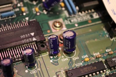
Note: Compared to the sub-board, the main board only has the negative leg position (the dot) printed on the board, the sub-board shows both negative (a dot) and positive (a '+' symbol) positions:
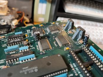 C1 (0.47uF, 50v), C5 (220uF, 6.3v)
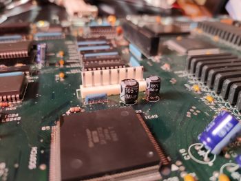 C12 (330uF, 16v), C13 (100uF, 16v)
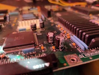 C15 (330uF, 16v), C16 (470uF, 6.3v)
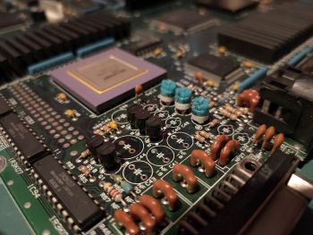 C38/39, C40/41/43, C44, C47/48/49 all cleared
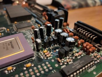 C38/39 (4.7uF, 50v), C40/41/43 (470uF, 10v), C44 (missing - awaiting part), C47/48/49 (4.7uF, 50v)
Main Board Complete
Sub-Board
Not looking forward to this one… there are loads of caps, and right near the audio section there's tons of them really close together.
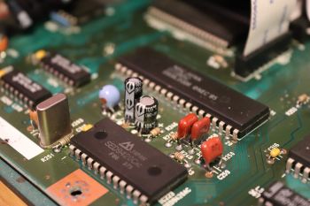 - C255 (4.7uF, 50v), C256 (47uF, 16v)
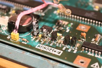 - C249 (1uF, 50v), C251 (22uF, 16v)
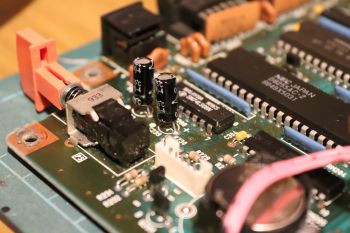 - C238 (0.47uF, 50v), C239 (0.47uF, 50v)
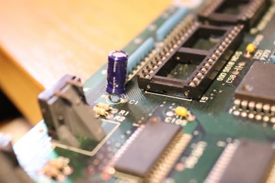
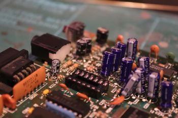 - C201 (100uF, 6.3v), C202/203 (100uF, 10v), C207 (10uF, 16v), IC203 (MC3403P Op-amp) removed & replaced with DIP-14 socket
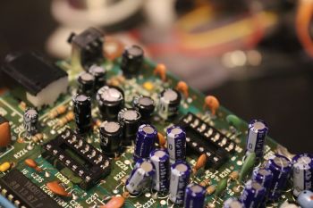 - C204, C213, C210, C211, C214, C215, IC209 (MC3403P Op-amp, replaced with DIP14 socket), IC201 (removed, waiting for DIP8 socket)
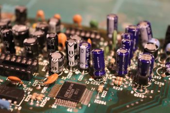 - C232, C205, C220, R221 (yes, this number isn't a capacitor, but it's the cap next to this part)
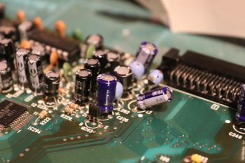 - [Update August 6th 2020] - C224, C227/231/C233
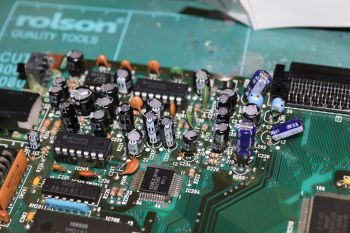 - [Update August 6th 2020] - MC3403P (x2 op-amps replaced & socketed), 2073D JRC (amplifier replaced & socketed)
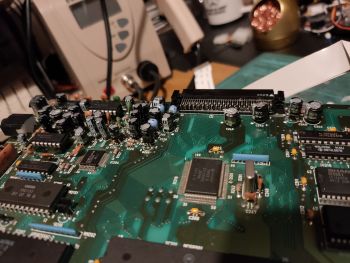 - [Update August 6th 2020] - C223, C225, C226, C240, C242 replaced
Sub-Board Completed
SCSI / Floppy / Audio Riser
Only 3 little caps on this small board:
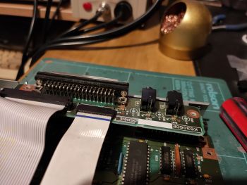 - Audio/Floppy/SCSI riser (C401, C402, C403, all removed)
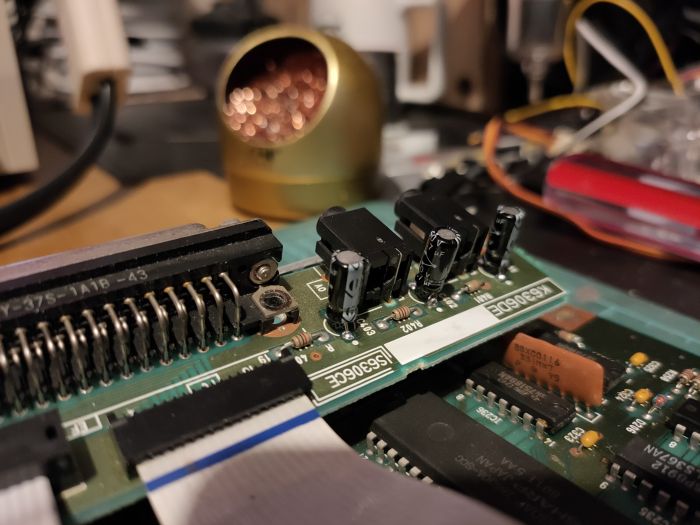
The board has the audio in and out jacks, as well as the external floppy and SCSI headers:
| Number | Location | Capacitance | Voltage |
|---|---|---|---|
| C401 | SCSI riser | 1uF | 50v |
| C402 | SCSI riser | 4.7uF | 50v |
| C403 | SCSI riser | 4.7uF | 50v |
SCSI / Floppy / Audio Riser Complete
Main and Sub-Boards Reconnected
Floppy Drives
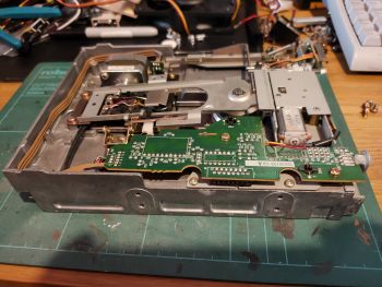
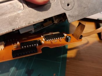
The floppy drives have several boards, each with capacitors that should be replaced.
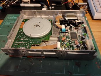
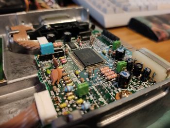 - Edge connector PCB (C1/2/3/4, C11/12, C23/24/25/26)
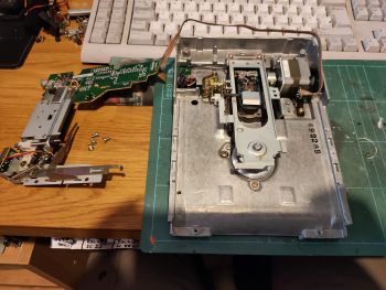
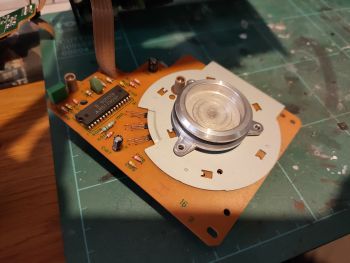 - Drive spindle PCB (C101, C104, C107)
Note: The capacitor lists here only apply to the X68000 Pro with floppy drive model “Sharp CMECF0015CE01”, also known as “TEAC FD-55GFR - Part numer 19307350-60”. Do not use this list for any other drive type:
| Number | Location | Capacitance | Voltage | Notes |
|---|---|---|---|---|
| C1 | Edge connector board | ??? | ??? | This is an all-black part with no rating label! |
| C2 | Edge connector board | 22uF | 10v | |
| C3 | Edge connector board | 100uF | 10v | |
| C4 | Edge connector board | 10uF | 25v | |
| C11 | Edge connector board | Ceramic, labelled as: SR 104M 12v | ||
| C12 | Edge connector board | Ceramic, labelled as: SR 104M 12v | ||
| C23 | Edge connector board | 6.8uF | 50v | |
| C24 | Edge connector board | Not fitted | Not fitted | |
| C25 | Edge connector board | 6.8uF | 50v | |
| C26 | Edge connector board | Not fitted | Not fitted | |
| C54 | Motorised eject board | 22uF | 25v | The only electrolytic cap on the board. |
| C101 | Drive spindle board | 22uF | 16V | |
| C104 | Drive spindle board | Ceramic, labelled as: 16X 100M | ||
| C107 | Drive spindle board | 0.47uF | 50v |
Remember that you need twice as many as listed above to do both drives, so the actual part list is:
- 2x 0.47uF, 50v
- 4x 6.8uF, 50v
- 2x 10uF, 25v
- 2x 22uF, 10v
- 2x 22uF, 16v
- 2x 22uF, 25v
- 2x 100uF, 10v
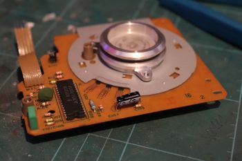 - Drive control board; C101, C107 replaced (make sure you bend or fit a low profile caps)
Logic IC Components
Not sure whether any of these will need replacing, but here's a list of all the discrete logic components on the board (excluding things like the sound chips, cpu, ram, video controller, etc):
Another Round of Testing
Audio Circuit Repair Test
Well the op-amp and amplifier IC replacement fixed the issue with no sound coming from the speaker unless you had your ear up against it:
It's still not the greatest in the world, but it's fine for a tiny little 0.5w case speaker.
Keyboard
Keyboard is still inactive.
Joystick Ports
Tried an MSX compatible pad in both port 1 and port 2, it doesn't register in Motos. The game won't let you start.
Floppy Drives
Floppy drive 0 still works fine. Floppy drive 1 still spits the disk back out as soon as you've inserted it.
Memory
The onboard 1MB, the additional 1MB from the IOData module and the extra memory on the XSIMM10ss card all test fine in memtest68k.
Booting Human68k DOS
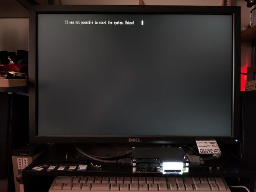
A Human68k dos boot disk still brings up the “It was not possible to start the system, please reboot” message.
So What Now?
I'm out of ideas with the system now. I think there is quite likely some damage to one or more of the IC's on the boards, but where to start with that, I've no idea. I don't have a scope and I don't have an electronics background.
[Update September 2020] - So I bought a 'working' X68000 Pro from Japan, planning to use most of the parts from it to make a fully working system… but upon arrival… well, see for yourself.
The plan now is to remove as much of the obviously unaffected components from the new 'donor' system as possible - desoldering chips, if necessary - and transplant them in to my 'mostly working' system that I've spent all of this effort on.
Stay tuned, I'll be posting more progress below.
The Final Curtain
[Update 24/02/2021]
After spending months more trying to get the system working I only just managed to get it booting a Human68k floppy - despite desoldering the last remaining surface mount chips from the IO sub board. Keyboard still didn't work, joystick still didn't work - making it completely unusable.
Tracing signals and low level logic debugging is not what I want to get in to, so it's time to draw a line under all of this and move on. Perhaps someone more adept than myself could get this running again. But that's it for me; I need to move on.
It's pretty sad to say that were it not for the incorrect PSU wiring diagram, this would have been an easy job and I'd have had months of fun playing with the system by now.
